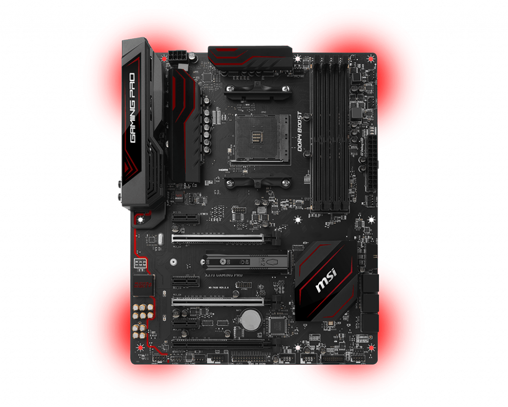
Since the NAS was going to be a typical tower and in the living room, the overarching goal was to make it also have the functionality of a gaming PC. To get true USB Hot-Plugging will require us to pass through an entire USB controller just like we did the Pascal GPU. We’ve covered the basics of IOMMU groups, and most server / workstation hardware (CPUs, motherboards, and chipsets) would make this pretty easy. However, I put this together out of older hardware I had laying around. Specifically, I have a Zen 1 Ryzen 7 1700 dropped into an X370 motherboard (MSI X370 Gaming Pro). Since all this hardware was made for “consumers”, the designers did not put a lot of thought into how things can be isolated and virtualized. So, the next step I need to take is to map all the IOMMU groups to actual devices on the motherboard.
Motherboard Architecture
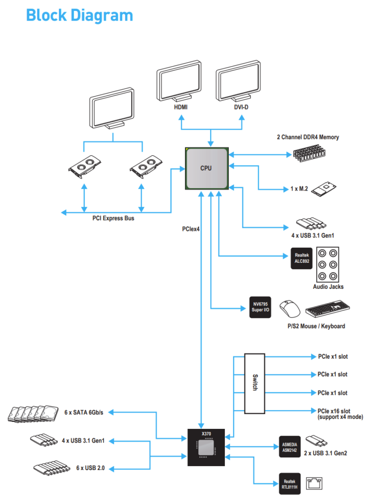
The first step is to get familiar with your motherboard manual (RTFM always). Usually somewhere inside is a “block” or “architecture” diagram. Manufacturers like ASUS are pretty good about this, but MSI didn’t lead us astray:
Typically (and this is NOT a rule), your CPU is going to have ACS (the fancy PCIe feature I talked about more here) at a minimum. As a result, devices attached to your CPU directly are likely partitioned into their own IOMMU group. This means that according to the architecture above, I should have IOMMU groups for:
- Each GPU slot
- The M.2 slot
- One USB 3.1 Gen1 controller (4 ports)
- The Realtek HD Audio
- The P/S2 port
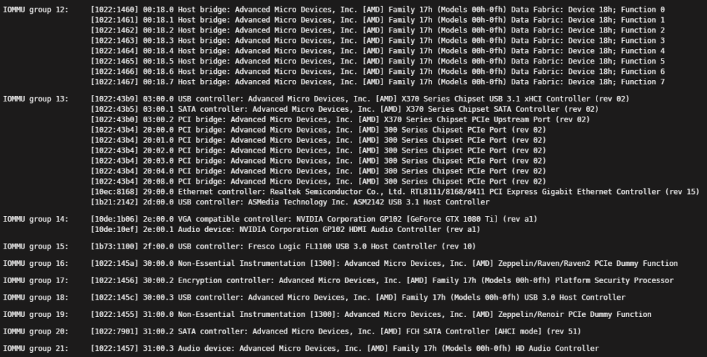
Sure enough, when we look through my IOMMU groups on my Unraid System Devices, we find that we have IOMMU groups for each:
- 14 – GPU 1
- 18 – A USB 3.0 host controller
- 20 – SATA controller for the M.2 slot
- 21 – HD Audio Device
Chipset
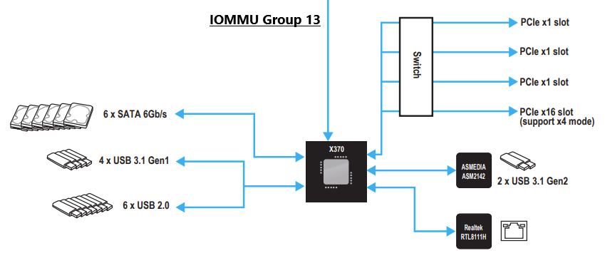
Beyond these devices, though, there are a lot of others. Namely, IOMMU group 13 above is a huge group of devices. This isn’t a big mystery, however. As you can see from the diagram above, I didn’t mention one big portion of it: the chipset. As you can see below, the kernel bundles the entire chipset and everything attached to it into one IOMMU group:
When I said the designers didn’t consider virtualization for these boards, I specifically was referring to this conglomeration of different devices. Importantly, the number of physical interfaces (e.g. PCIe slots and USB ports) attached to this chipset causes difficulties in splitting up devices logically. This is where most people find themselves when they resort to just breaking up this entire chipset in order to split off individual devices by turning ACS Override on. Our mission is to specifically avoid using ACS Override for security and stability reasons. To do so, we will track down which PCIe and USB controllers are attached to the chipset and which are attached to the CPU.
PCIe Devices
After seeing the Block Diagrams above, it’s quite easy to map these back to the PCIe slot diagram from the motherboard manual:
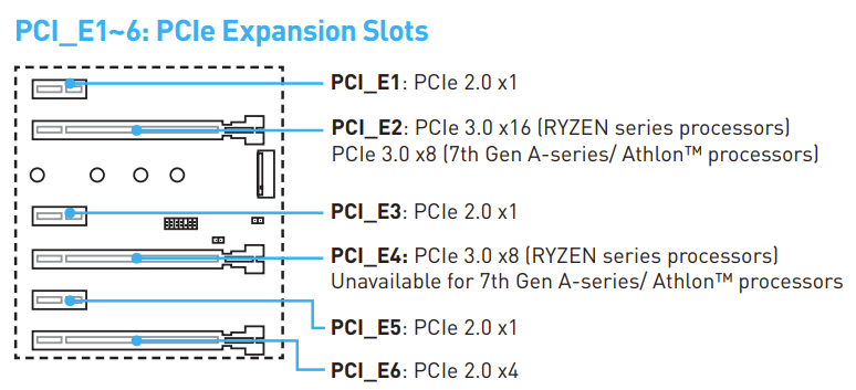
This motherboard has 6 PCIe slots: the CPU controls two (2) of them, and the chipset controls the other four (4).
| CPU | Chipset | PCIe Gen | |
| PCI_E1 | X | 2 | |
| PCI_E2 | X | 3 | |
| PCI_E3 | X | 2 | |
| PCI_E4 | X | 3 | |
| PCI_E5 | X | 2 | |
| PCI_E6 | X | 2 | |
| M.2 | X | 3 |
The PCIe x1 slots as well as the last PCIe x16 slot are all running PCIe 2.0, and match up with the block diagram above as it notes 3 x1 slots and a x16 (x4 logical). The CPU connects to other devices at PCIe 3.0 speeds, so it’s a good double-check that all of the CPU-connected devices also show PCIe 3.0 on the PCIe diagram above.
As far as IOMMU groups go, these PCIe 2.0 ports are all within the IOMMU group 13 above as “300 Series Chipset PCIe Port”. This means anything connected to the PCIe 2.0 ports will all connect to the X370 chipset, and will thereby be added to that large IOMMU group. In order for us to have any hope of passing PCIe devices through to VMs while not using ACS Override, we’ll need to make sure that it’s connected to a port that connects directly to the CPU on PCI 3.0 for this motherboard. With a GPU installed in one of the two ports, we only have a single port left that will allow us to PCIe pass-through.
Conclusion
The architecture and configuration of consumer motherboards like this MSI X370 board I have are limited in the number of isolated IOMMU groups they have. As we found above, this board really only has TWO out of the six slots available for PCIe passthrough: those both connected to the CPU directly. One of these in my configuration is already taken up by the GPU, so any other card would have to go into the other GPU slot, limiting the number of devices I can install. In the future, we’ll touch on a couple of the other devices on the motherboard, namely USB host controllers, that we can repurpose.
References
- https://access.redhat.com/documentation/en-us/red_hat_enterprise_linux/7/html/virtualization_deployment_and_administration_guide/sect-iommu-deep-dive
- https://mathiashueber.com/pci-passthrough-ubuntu-2004-virtual-machine/
- https://forum.level1techs.com/t/using-acs-to-passthrough-devices-without-whole-iommu-group/122913/4
- http://vfio.blogspot.com/2014/08/iommu-groups-inside-and-out.html
- MSI X370 Gaming Pro motherboard manual
- https://www.reddit.com/r/VFIO/comments/klz8rd/a_bit_confused_about_iommu_groups/
Hi, I appreciate the info shared here. I’m getting this board and l’m hopeful I’ll get the functionality I need or at the very least will learn a thing or two. Will look for more in future from you.